Tag electronics

Automate Everything

Over the years I’ve messed with various home automation systems. From X10 in the early 2000’s, through Mi Casa Verde and z-wave going into the 2010’s, a few years using OpenHAB, up to the current day where I’m using Home Assistant.

Home Assistant has been around for a while, but I was loathe to move from OpenHAB as I already had a lot set up. However, as OpenHAB fell behind I finally bit the bullet and installed HAOS on a spare Raspberry Pi. This turned out to be a good thing.

I’ve been using it now for a couple of years, and it works really well as a central hub for all the different technologies in the house. This post is a quick overview of what I have set up.

Technologies

The beauty of Home Assistant is that it acts as a hub for many different home automation protocols, devices, and other information. A quick list of technologies I have integrated:

  • Zigbee
  • Z-wave
  • ESPHome
  • Matter
  • Thread
  • MQTT
  • WLED

But not only does it talk to these home automation systems, it can also tie into other things such as:

  • 3d Printers (Octoprint, Klipper, Bambu Labs)
  • Google Assistant (Ties your home automation into google voice commands)
  • Jellyfin/Plex
  • Fitbit
  • Raspberry Pi
  • Roomba
  • Smart Meters
  • Printers (you know, the none 3d kind)
  • Frigate (CCTV)
  • Solar Production

And lastly, you can pull in information from web APIs to help with automations:

  • Weather
  • Sunrise/Sunset
  • Moon phases
  • Astronomy Weather (More detailed weather more geared to astronomers)
  • Github (Monitor commits, issues, etc.)
  • Whois (Keep an eye on domains expiring)
  • DVLA (MOT and insurance due dates)
  • Waste Management (get dates and types of refuse collection)

This is a lot of tech, and this isn’t a complete list of everything I have tied in, just the majority.

My Setup

So, enough of what it can talk to. How is my house set up?

Core

The main core of the system is a Raspberry Pi 4 running Home Assistant OS. This is a simple install onto a Pi and is fully managed by Home Assistant. Everything runs in containers and gives you everything you need to get started.

The Pi is run from PoE in a rack, to keep things simple, and also has everything installed onto an SSD drive as it is a lot more reliable that using an SD Card (My old OpenHAB system was on SD Card and I had to rebuild it every now and again as the SD card wore out). Plugged into the Pi are two USB dongles, one for z-wave and one for Zigbee/Matter. This direct connection lets me control the majority of the devices I have.

Also, installed as part of HA OS I have a few other addons. These are:

  • InfluxDB – This keeps a historical record of all the stats in the house, which can then be pulled out into a Grafana Dashboard
  • Mosquitto MQTT Broker – Some devices talk directly to an MQTT server, so this is running to fill that role
  • ESPHome – A system designed to convert simple ESP32 or ESP8266 boards into home automation devices using a simple yaml language. Some commercial devices can also be flashed with ESPHome for extra functionality.
  • HA Google Backup – Backups!!
  • Lets Encrypt – Automatically renews my SSL cert
  • VaultWarden – A locally run version of Bitwarden password manager.

These are all running on the same Pi quite happily.

CCTV (Frigate)

I have a second Pi 4 running a system called Frigate. This is an open source CCTV system that integrates really nicely with Home Assistant. It also has functionality for not only motion detection but facial detection too so that it will only trigger if it detects a human (not a cat or squirrel) which definitely helps cut down on false positives. I have had to block out certain areas for detection tho, as in high winds it sometimes thought some of Joy’s flowers were a human!

I’m hoping to upgrade this to a Pi 5 when the PoE hat comes out, as I currently have 4 cameras going into it and it does struggle a bit. I do have a USB Coral AI stick from Google that I can offload some of the more AI related tasks too.

NAS (TrueNAS Scale)

I do have a NAS box set up that has a simplified Kubernetes system installed. On this I run a few other services, including Grafana for viewing stats of my home, Spoolman which keeps track of my 3d printer filament usage, and Trilium Notes for keeping track of the random things in my brain.

Other Hardware

So what have I actually got set up?

Most of the main lighting in the house are Phillips Hue lights, with their dimmer controllers. However, since realising just how much data the Hue hub was sending back, I removed that and now everything is directly controller via Zigbee. The only main exception to this is the garage which initially had fluorescent tubes and I use a z-wave in wall module to control that.

I’ve a lot of smart sockets around the house too, from plugin units to actual in wall faceplates. The vast majority of these allow for energy usage collection too so I can not only turn things on and off remotely, but I can also monitor the energy usage of various items such as 3d printers, server cabinets, desktops, TVs, etc.

The burglar alarm is also connected in, which turns all the various door and motion sensors into sensors that Home Assistant can use for automations.

WLED is a system to install onto an ESP8266 or ESP32 to control a string of RGB LEDs. I’m starting to incorporate more of these into the setup and they tie very nicely into Home Assistant

Control

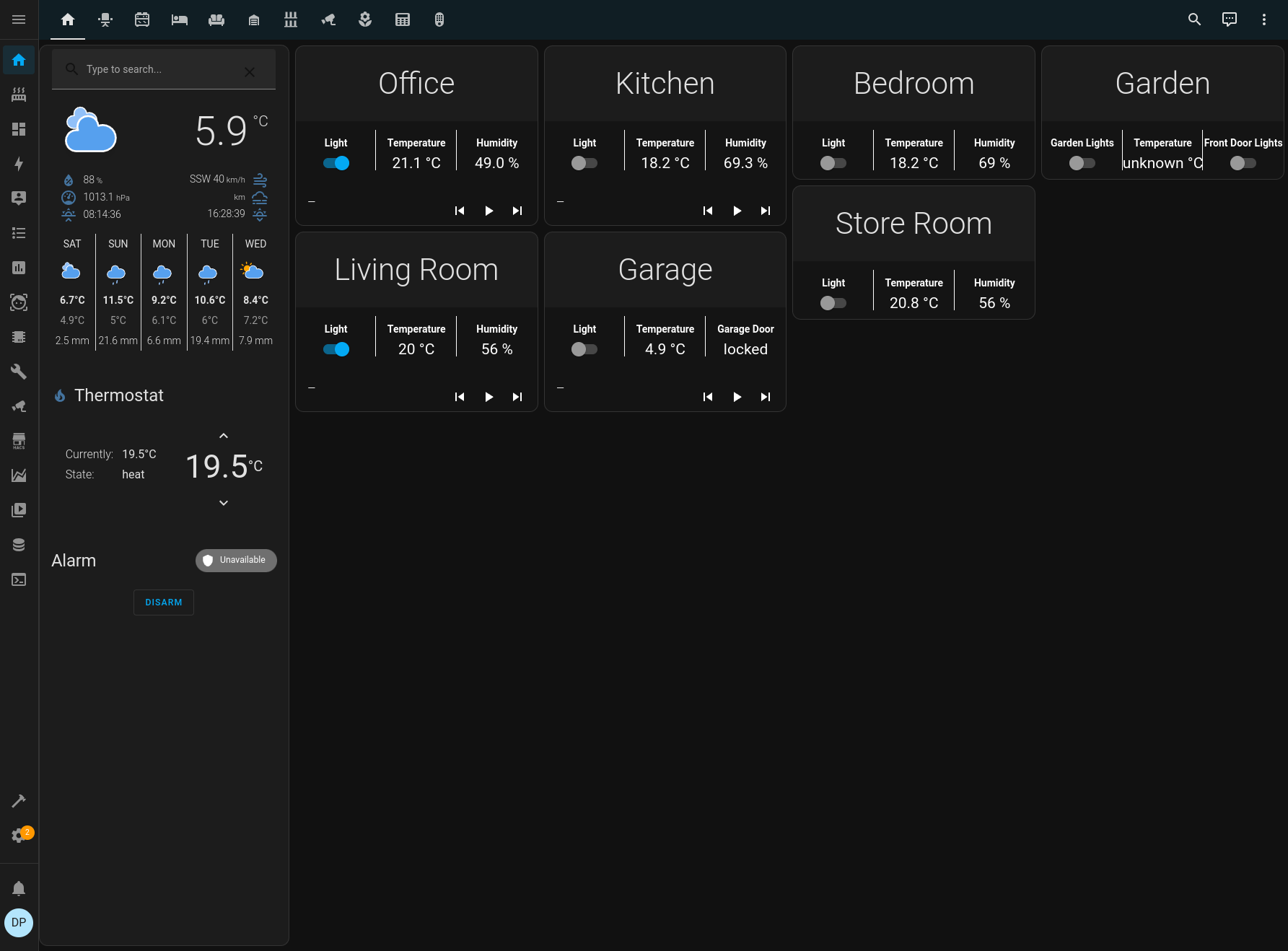
What does all this gain me? The main benefit is a single app on my phone to control everything. I don’t need a Hue app, a Roomba app, to access a webpage to control my WLED lights, etc. I can create a dashboard on Home Assistant to give me a nice overview of the controls in the house. For instance, my setup main dashboard consists of an overview page (simple controls such as lights, along with main thermostat control and some other status) with the ability to click a room and get more detailed controls and information. That covers about 90% of everything.

Along with this, as I have Google Assistant integrated, I can also just ask google to turn lights on, set the thermostat, etc.

Automations

So far, most of the stuff is just allowing for remote control, but the real beauty is making things automatic. I’ve only really got some basic automations done at the moment and want to expand on this in the future.

  • Automatic outside lights. I have the lights set to come on at sunset, and turn off at midnight. They’ll also come on in the morning if Joy is going to work and its still dark out.
  • Turn the thermostat down at night. The thermostat will drop a couple of degrees at midnight whilst we’re asleep to save some energy. I have got the alternative set to turn it back up in the morning, but thats disabled for now as its just as easy to turn it up manually depending on what time we get up.
  • Send an alert if someone comes to the front door, and turn the light on. This is one of the reasons I want to upgrade the Frigate Pi. The Pi 4 is just a little slow on this, and hoping the extra processing power will speed things up.
  • Show video feed on my google home displays when someone is detected on the front door camera.
  • Automatic office lights. I’m terrible at remembering to turn my light off in the office, so I have a simple motion detector to automatically turn the lights on and off. They do turn off occasionally if I’m in the office concentrating on something and not moving much (such as writing a blog post about my home automation system) so I’ve just ordered some mm wave detectors to try which should be more sensitive.
  • Notifications when prints have finished or theres an issue.
  • Daily notification if a battery is low in a device. All my Phillips Hue Dimmers were bought at the same time, and I’ve just had to replace all the batteries at once!

Theres room to do a lot more of course, but these will do for now.

Monitoring

So, I’m a nerd and I like stats. One of my favourite things that Home Assistant does is store historical data so that I can pull information out and graph it in Grafana. I’ve no idea if this will have future uses, but it does produce some pretty pictures such as the one on the left that shows temperature and humidity over time.

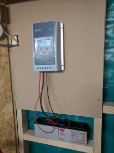
Also, Home Assistant has an inbuilt energy dashboard. You can select the various entities you monitor for energy usage from smart meters or solar panels, and it will generate a nice dashboard to show your energy usage.

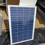
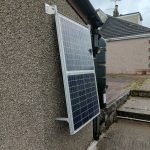
Water consumption is on there because it seems UK water meters broadcast their readings unencrypted on a band that can be read with a cheap USB dongle. I wrote some python to read the meter and push the stats into Home Assistant. I also wrote some software to run on a Pi connected to my two solar systems to read the meter information there and push it into Home Assistant.

I’m hoping once I’ve collected data for a full year, I can work out if I can get a decent ROI on a house battery.

Future Plans

One of the big things at the moment is LLMs (I won’t call them AI!) and Home Assistant can actually make use of them right now. This means I can replace all my spyware Google Homes with a fully local solution running on some low powered Raspberry Pi zeros, using a local LLM for more natural language communication. Plus you get the ability to add custom wake words, which will be fun.

I’ve also got a Pi with a 10 inch display on my desk that I want to turn into a control panel to put somewhere in the house, possibly in the entrance way.

Tracking the skies

SDR Radios

One of the things I’ve been getting into recently is using Software Defined Radios (SDR) with cheap USB digital TV tuners that are available all over ebay, etc. These have been taking the radio community by storm as the chipset in them from RealTek can tune into a really wide band of frequencies. Usually from down around 20MHz, all the way up to nearly 2GHz.

Typical Digital TV stick with the Realtek chipset in

Tracking the skies

One of the fun and cheap projects you can do is track all the aircraft that are flying around you. All commercial and some light aircraft are required to have an ADS-B transponder that sends out a radio signal on 1090MHz that contains their location, speed, etc. These signals can be received with one of these SDR dongles and decoded to display this information on your computer.

There is even a ready made piece of software called dump1090 (and many, many forks of it) that will also display this information on top of a google map.

Current view of the planes around me

Antenna

The first thing you will need is a decent antenna for receiving these signals. The easiest to make is a quarter wave ground plane. In the simplest terms, this means that the main part of the antenna is a quarter of the wave length of the signal. The equation for this is:

f = c / λ

where f is the frequency, c is the speed of light in m/s, and λ is the wavelength. So to get the wavelength of 1090MHz, you rearrange the equation to:

λ = c / f

Putting the correct numbers into this means that a quarter of a wavelength is just 68.8mm. This makes for a pretty small antenna.

The ground plane is just four more wires at 90 degrees to each other, and bent down at a 45 degree angle.

All these wires are then soldered into a standard SO239 panel socket.

A quarter wave ground plane antenna for 1090MHz

There are many sites that will give a much better walk through of how to make one and the details behind it.

Software

Next, we need to look at the software. At this stage, if all you want to do is have a quick look for some fun, all you need is the antenna, usb stick, and the dump1090 software from one of the many forks (If found the dump1090-mutability one to be best). Download or clone this repo, and follow the compile instructions to give it a try. You should then be able to view the results either on screen or via a web browser.

The other option if you are going to go for a more permanent solution is to maybe use the data to improve a commercial sight such as FlightRadar24. This is what I chose to do, so I signed up for an account with them and followed the instructions to build a dedicated Raspberry Pi receiver that will automatically upload any information I receive to their systems, hence improving their reliability. This also gets you a full business account on there worth $500/year!

Enclosure

Lastly, if you’re doing a permanent solution, you need somewhere to put it. To save space and cost, I just used a Raspberry Pi with an decent sealed enclosure box.

Setup without the enclosure

I used some epoxy to glue the antenna on the end of some 20mm conduit that I had, with the cable passing down through it. Then drilled two holes in the box. One that I put a rubber grommet in to pass the power feed through, and the other to put an external antenna connector through.

Lastly, I used epoxy again to fasten some 20mm brackets to the box lid for the antenna to attach to. This was better than screwing, as fewer holes for moisture/bugs to get in through. Then I just mounted the whole thing on the side of my garage and passed a cable for power to it.

The whole unit is attached to the side of the garage

Ideally it would be placed higher, or at least the antenna would be, but that started to make things complicated. As it is, I can still get signals from planes nearly 200 nautical miles away.

Summary

Now I can access the Pi whilst I’m on my network and view all the planes around me. I also have a full business level account with FlightRadar24. Is there much point? Nope, not really apart from helping crowd source data for a company. Why’d I do it? Because I can and its fun!

A bit of Solar

I got a message a few weeks back to see if I was still looking for old laptop batteries for 18650 harvesting, and of course I said yes. The next day, I got one or two batteries dropped off at my house:

A few crates. There were a couple of other ones too.

A few crates. There were a couple of other ones too.

Wow. Its going to take some time to crack them all open, harvest the cells, and test them all properly. Of course, I’ve got two batteries for R2 now that seem to be in a good shape and last long enough for pretty much any event. So the question is, what do I do with all the cells I’m going to have once I’ve finally gone through all these crates.

I’ve a few projects in mind that will utilise a couple of cells each, including a standby battery for R2’s brain, but a rough calculation shows that once I’m through all these crates I’ll have approx 1200 cells of varying states. So far, I’m through about half a crate and the vast majority seem to be in a good condition and over 2000mAh capacity. That means I’ve got nearly 8kWh of energy storage! Even if I assume half the cells are dead (so far only about 2% seem dead), thats still 4kWh.

The first thing that jumps out for this amount of storage is a form of power wall. Now, I’m not going to do anything grid tied, that is just too much hassle, but doing something off grid for the garage is definitely doable. If I can perhaps do enough to run the computer and other electronics, plus indoor and outdoor lighting, then I will consider it a success.

25W solar panel for testing

25W solar panel for testing

To start the project, I got hold of a few small solar cells, one 25W, and a couple of 50W ones. The 25W one will be used for experimentation and testing theories out, and the two 50W panels will be mounted on the wall of the garage for a more permanent solution. I also purchased an EPSolar MPPT charge controller, to go with a couple of spare 12V SLA batteries I had spare from initial testing of R2. I went for this model as it has a serial out port on it that will allow me to tie it into my OpenHAB home automation system and graph things like battery charge, solar power production, and any load on the system.

Fabricated a couple of brackets to mount the 100W combined solar panel

Fabricated a couple of brackets to mount the panel

Being able to graph those details will allow me to make an estimate of how much energy I can generate on a typical day, and from that calculate how much I can actually run off my system for a given amount of solar panels, and also work out just how many kWh of energy storage I need.

The charge controller however will only work with standard lead acid batteries, whilst I want to make use of the 18650 cells. To this end, I did a lot of reading and it seems that there are very few hobby level solar charge controllers that will work properly with lithium technologies. Some charge controllers can be made to work with them, but it is more of a bodge.

After much searching, I did find one chinese charge controller that said it worked with lithium batteries, and actually seemed to back that up in the details. One of the main things to look for is that it supports the typical CC/CV (constant current/constant voltage) charge methods that are required for all lithium cells. A few clicks, and it was on its way on a slow boat from china.

Solar charge controller mounted

Solar charge controller mounted

For now, I’ve got the EPSolar charge controller mounted on the wall of the garage, connected to the 100W of panels outside.

Next steps are to get some data logging from the serial port, probably using an ESP8266 based device, dumping the data into my MQTT server, which in turn will be monitored by OpenHAB to be dropped into an influxDB store for graphing with Grafana.

Along with this is the slow process of breaking open a lot of laptop batteries and harvesting the cells. Once I have enough for a decent sized test, I will be looking into various ways of mounting them and hopefully adding an individual fuse to each cell for safety. More research into BMS for making sure the battery is properly balanced is required too.


Building a battery for R2 with 18650 cells

There are many options for a battery to power an astromech, from the tried and tested Sealed Lead-Acid, to the latest LiFePO4. This article will look at utilising the very common 18650 cells. These are used in power tools, laptops, even Tesla cars.

WARNING, this article will talk about opening old packs, harvesting their cells, soldering cells, spot welding cells, and lots of other things that could be quite dangerous.

Lithium cells of any type can heat up or burst into flames if mistreated. Only attempt the things in this article if you are entirely comfortable with any possible outcomes. Do other research, read other articles, the author accepts no responsibility for any injuries or death from the instructions given.

General theory

18650 refers to the size of the cells, 18mm x 65mm. They generally have a capacity between 1500 and 3500mAh. If you see anything saying 4000mAh or above, chances are its a scam. There are a lot of cells branded ultrafire that claim over 6000mAh capacity which is a total lie. Voltage ranges from 4.2v when full, to 3.2v when empty. These cells use Lithium-Ion technology, which is a lot safer than the Lithium Polymer that is used in many radio control devices. The drawbacks are that it has a much lower discharge rate. LiFePO4 are even safer, but are also more expensive. Li-Ion seems to be a middle ground, which is why it is used in so many places.

Generally, these cells are arranged in series/parallel to get the desired voltage and capacity. For example, a 24V battery is made of 6 cells in series. Extra capacity is added by putting more cells in parallel, so that if you use cells with 2500mAh capacity and want a 24V battery with 10Ah capacity, then you will use 4 rows of 6 cells, commonly written as 6s4p.

The current drain allowed on a battery is usually 1C, or 1*<capacity>, so in the same example 6s4p battery, you can have a maximum drain current of 10A. Doubling the battery up to be a 6s8p will give you 20Ah and a 20A potential drain. 1C is the safe limit using recycled cells. If you are using brand new cells then you may be able to get a higher current draw by checking the datasheet. For example a NCR18650B can draw 2C and a NCR18650PF can go up to 3C.

Sources

Cells

As mentioned above, 18650 cells are used in many places, and can generally be recycled. The best place I have found for second hand cells is from laptops or power tools. These battery packs can be cracked open and the cells removed. It is quite a labour intensive task, but saves a lot of money. You can pick up job lots of second hand cells from eBay, tho this is getting more expensive as more people are harvesting cells this way.

You have to force the two halves of the battery case apart, usually with a screwdriver or similar flat sharp object, and then separate the cells from the circuitry and cabling inside. Always wear heavy gloves, and take extra care when using a lot of force. Its easy to slip and damage yourself or the batteries. Also make sure to take care not to use the cells as a fulcrum as this will also damage the cell. Basically, be careful and take your time.

An Opus BT-C3100 18650 charger/tester

The drawback is that each cell is of unknown capacity and life, some cells may even be totally dead. They could already have been through a few thousand cycles. Each cell needs its capacity testing with a charger/tester such as the Opus BT-C3400. Of course, if you can ask friends and family for donations of old laptop batteries, you can save even more money. I managed to get a lot donated for free. Despite the drawbacks and amount of work required, you can end up with a battery for next to nothing that would cost a lot if you bought a ready made one. For example, I built a 24V 25Ah (approx) 6s11p for around £50 of cells, plus a few other bits.

The other option is to buy brand new cells in bulk. Either from Chinese sites such as aliexpress.com, or from other sites closer to home such as eu.nkon.nl. Chinese ones are generally a little cheaper, but you do have a long lead time and the risk they are counterfeit. A typical cell such as the NCR18650B (high capacity/average discharge rate) or NCR18650PF (medium capacity/high discharge rate) can be bought for approx £3 a cell.

Additional

As well as the actual cells, there are a couple of other essentials. These are cell spacers, which clip into various configurations to hold the cells in place, and allow air flow around them. You’ll also need nickel strip to connect all the cells together. Both of these items can be bought from aliexpress.com in bulk. If you are buying brand new batteries from NKON, they also sell nickel strips for a decent price when bought in batches of 10m.

Lastly, you’ll need battery connectors and a balance lead. The battery connector can be anything you wish, as long as it will take the current. The balance lead is a connector so you can make sure that all the series cells are at the same voltage. This is important so you don’t let one cell run down lower than the others, which will potentially damage the cell, and maybe the whole battery. You need one for the correct size of battery (eg, a 6s battery will need a 7 wire balance lead) which can be got again from aliexpress.com or ebay.

Constructing the battery

Once you have enough cells together, and all the other items, time for construction. The general process is:

  1. Sort the batteries into parallel sets with the same total capacity. The idea is to have them well balanced before you even start. You can use a site such as repackr.com to help with that
  2. Clip the cell spacers together in the required layout (eg 6×12 for a 6s12p), then lay the cells out. Each parallel set should be the same orientation (eg, negative to the top), but alternate them as you fill in the series set.

    The start of a 6s12p pack. Can see the parallel sets run down the picture, with the series sets alternating across

    The start of a 6s12p pack. Can see the parallel sets run down the picture, with the series sets alternating across


  3. Once you have all the batteries in place, clip the top of the frame into place

    Here is a small 3s5p pack, ready for the nickel strips

    Here is a small 3s5p pack, ready for the nickel strips


  4. Now its time to connect the parallel sets up. Using either a soldering iron, or a spot welder, connect strips along all the parallel sets. These are the ones that are all the same way up. What this does is create the capacity for battery pack. Be careful if soldering, don’t allow too much heat to build up on the cell, do it as quick as possible. You can get spot welders from aliexpress.com for around £200 that will do the job a lot better.""

    You can also get a device that will give you a full readout, just from plugging the balance connector in. They are only a few pounds from places like ebay. They will let you view the total voltage, each parallel set voltage, and also the max/min/dif between the cells.

    Balance capacity checker

    For the initial charge you will need to use a decent balance charger, such as an imax B6. These are generally for lipo batteries, used in radio controlled quad copters or planes. The benefit of a charger like this is that it will balance the cells out and has lots of monitoring and protection built in. Follow the instructions in the charger manual closely.

    Testing

    Once charged, leave your pack for a while, even a month, testing the voltages periodically. If you have a dead cell, then it can manifest as one of the parallel sets slowly loosing charge. When this happens, you’ll have to dismantle the battery and retest all the cells.

    If you have the time, you can also do a full discharge test with the charger on the battery to get an accurate reading of its capacity. This will take a long time if you’ve made a big battery, depending on the charger you use. If you aren’t overly bothered about an accurate capacity test, just run the battery in the droid (or whatever other use) and monitor the voltage. Don’t let the voltage go down below 3*<number in series> (eg, a 6s should never be let to dip below 18v). To prolong the life of the battery, don’t even let it go that far. Full charge/discharge cycles are the worst case for wear on them, and will shorten the lifespan. I recommend discharging it to around 40-50%, at least on the first try.

    After the first discharge, check the balance of the cells again. Ideally there should be little difference between them in a fully functional battery pack. If there is significant difference (IMHO, 0.1v between the highest and lowest voltage) then you may have a bad cell somewhere. Do another balanced charge and discharge cycle and see if the same cell has troubles. If it does, rip it apart and try again.

    If the battery remains balanced, then you can actually use a none balance charger (cheaper, and usually higher current for rapid charging) for most charge cycles. Tho make sure it is balanced occasionally and no harm in doing a slow balanced charge once in a while.

    Conclusion/Notes

    Using 18650 cells gives you great flexibility in not only the size (voltage and Ah), but also the shape. This example has shown creating standard blocks, but with some creativity you can make a battery that follows a certain shape (ie, follows the outer curve of an R2 unit’s interior). If you want to make use of recycled cells, then this is a very cheap option to get some very high capacity batteries built. Even buying brand new cells will still save you a lot of money.

    For example, I’m currently building a 6s12p pack using NCR18650B cells. I’m getting these for approx £3 a cell. That makes the total cost of cells £216, which gets me a 24V/40Ah capacity battery in a fairly small form factor that can give out nearly 80A (my droid barely pulls 10A at full speed!). I doubt I could fit enough SLA batteries in my droid to get that, and a similar capacity of LiFePO4 would set me back about £800. Even taking into account the cost of a spot welder (which can be used many times of course) its double the price.

    Further research

    One thing I haven’t covered in this article is a BMS. This is a Battery Management System makes sure nothing is going wrong with it, and will cut off the output when the battery gets too low. I’m still researching these myself, and will possibly mess with them on my next pack. IMHO, if you are keeping an eye on the battery voltage during use and doing periodic balance tests and charges, then a BMS is not necessary.

    Also note that capacity of the cells will drop over time, depending on number of cycles, how deeply they were charged/discharged, and how rapidly they were discharged. Take care of the battery, and it will last longer, drain it constantly at high current and it will be dead within a few hundred cycles.


Remote observatory

Ok, so remote means just a few meters away, either in the house or in the car. Somewhere warm anyway.

So, as mentioned in my previous post, I’d done a lot of research, and one of the things I came across was this video:

This is what I want to be able to do. I’ll never have the room for an actual observatory like this one, but I could at least automate a lot of the work. That’ll scratch at least two, maybe three, of my geek itches. Of course, everything has to be Linux based, and also as cheap as possible. With that, I decided on at least the following to start with:

  • AstroEQ – Definitely needed goto support on my EQ5 mount to start with.Fully made systems can be bought (minus steppers and mounting hardware), but I already had most of the parts laying around the place so decided to make it myself using an Arduino Mega
  • Indilib – This, running on a raspberry pi acts as a remote control server for anything that I wanted to add. All devices had to be supported, or easy enough for me to add with my limited programming skills.
  • Guide Scope – These are used to ‘lock’ onto a star and make sure that the telescope mount follows it precisely. Long exposures of up to even 30 minutes can then be achieved without too much difficulty. Initial plans are to try and use the Raspberry Pi camera (will try both standard and NoIR) versions.
  • Focuser – Last essential part for remote control is the ability to focus the telescope. This will use the DSLR attached and a stepper motor coupled to the focus knob. There are a couple of arduino based projects that emulate the MoonLite protocol, which is supported by indilib.

Once I’m happy with this lot (and I *will* blog my progress) and have some of my other projects finished (*cough* R2), then I want to take a look at a couple of other add ons such as:

  • Filter wheels – I can use kstars to take many photos with different filters in place, and also with a black filter I can automatically take dark frames for stacking images. (Dark frames are used to remove noise in the picture that is generated by the DSLR)
  • Auto lens cap – A simple servo driver to cover the telescope main lens. Not really necessary, but figured it would be a nice project.

I should be able to do all of this fairly easily. I already have most of the components necessary, and the software running on my workbench. One of the big issues I’ll need to work on is just how to mount it all to the scope and stop the cables getting tangled!

My next blog should be on building and configuring the AstroEQ.

Another hobby?

Hi, my name is Darren and I’m a serial hobbiest.

Well maybe not that bad, most of my hobbies are pretty much related (electronics, computers, science), and a lot are things I’ve been interested in since I was a kid. Most recently, I’ve invested in a fairly decent telescope and mount to do some visual astronomy, but more for astrophotography. I want to take pretty pictures of things very far away! So after a lot of reading of various blogs and websites (Star Gazers Lounge forum is fantastic), and watching numerous youtube videos, I got a tripod for my camera and a couple of cheap lenses off eBay. That is all that is needed and you can get some half decent shots.

My astrophotography album

But it wasn’t enough. So I dove back into the forums and did even more research, and learnt a few important things.

  • Telescope – Numerous different types, mainly split into reflectors, refractors, and catadioptric. All have their benefits and downsides, but for doing astrophotography the telescope isn’t the most important item surprisingly.
  • Mount – This, for astrophotography, is the most important thing to get right.You need to have a solid mount for doing anything more than a few seconds exposure, and one with tracking in Right Ascension at least, to track the stars. And it really needs to be an equatorial mount to avoid rotation of the starfield as it rotates.
  • Eyepieces – You need eye pieces to view through a telescope, and the shorter the focal length, the greater the magnification. These are generally only used for visual astronomy, as cameras bypass the need.
  • Camera – Most DSLR cameras block out a large part of the infra red by design, but you can get them modified to remove this filter and get much more vibrant images. Its not a necessity, but definitely a nice to have.

Whilst learning all this, I had a thought in my head about some form of computer control (Linux based, of course) and actually stumbled upon a few projects to help with this. The first was AstroEQ which was an opensource ‘Goto’ system (select a star, and the telescope will automatically move to center on it) designed around an arduino. That was a perfect start for me, and I was pretty sure I could get it working from Linux. Thats when I discovered indilib!

Indilib is an open source system for controlling all sorts of astronomical instrumentation, not just goto mounts, but also things like auto focusers, digital camera, filter wheels, and other custom devices you may want. Even better, all this can be run from a Raspberry Pi as the control server and a laptop using the actual astronomy software. This would mean I could set it all up, and retreat to somewhere a little warmer to actually do my observations and photography. I’m sure this is against the amateur astronomers code or something, but damn it gets cold out there.

Along with indilib, there is kstars. This is a planetarium program written for the K Desktop Environment, and with EKOS plugin can control any indilib hardware. Not only that, it can schedule work and sequences, and help you plan your observations.

I’m going to (try to) write more blog posts chronicling my progress on getting all this set up, and some HowTo posts on using indilib on a raspberry pi, with kstars, and any custom hardware I make.

Slow but steady, or not…

It seems that xmas and new year is when all the part runs start. At least that is what it feels like to me, for all the parts I want.There has been a sudden rush in ordering things for R2 which means I nearly have everything I need to get him put together and mobile. The one part I’m still missing is the outer ankles, which I am hoping will be on a run soon. The last few cosmetic pieces I need are due soon too, such as utility arms and LDP. Progress whilst waiting for these parts has not been too bad, but I do keep coming across problems to work around. I guess that is the fun part tho.

On the electronics front, I managed to (I think) blow up my amplifier. I still need to hook it all up again and test it. I’ve a feeling that the switch I’ve got for main power isn’t rated high enough for the current that is going through. I’ve also decided to change the layout of everything, and install an actual touch screen inside R2 for the Raspberry Pi. This will give me the ability to control certain aspects of the software, and also at a pinch I can plug a usb keyboard and mouse in to do onsite programming whilst away at a convention or such like. I’m also currently waiting a Raspberry Pi v3 which will give R2’s brain a bit of a boost. Overall design hasn’t changed much, it’ll still all be controlled via i2c, but will also have wifi and 3g internet connectivity, turning R2 into a wireless hotspot! I will have to see how much the aluminium body affects the signal, but can always put an external antenna somewhere.

IMG_0298_CR2_embeddedI have more or less got the legs finished, and have done a test fit! Must say, they are looking rather good. All the parts slot nicely together and are pretty solid. Of course, I still have the problem of a lot of the screws and bolts being imperial (We’re part of the rebel alliance, don’t want any of that imperial rubbish!) rather than metric, so getting hold of replacements can be tough. This is more of a problem seeing as I’ve had some of these parts for quite a while and not only been moved around the office in the old house, but have moved to the new house and gone in and out of the garage, so some of the fastenings have been misplaced along the way.

I also decided to get one of the nice new hydro formed domes that are available. I was never too keen on the existing one that I had, and the new domes come with the mounting ring to fasten it to the body which meant one less thing I had to fabricate. A lot of the tutorials on the forums are geared around these domes too. Not only did I get a new dome, but I figured whilst I was doing that, I’d also upgrade all the things to go in the dome. This meant getting the ultimate hinges, aluminium holoprojectors, aluminium logic surrounds, aluminium eye, and even the fancy PSI holders. All this together gives me a pretty much top of the range dome for R2. It also means I can do a quick and dirty rebuild of the old dome at some point and create a different astromech.

IMG_0304_CR2_embedded IMG_0309_CR2_embedded IMG_0489_CR2_embedded
Which brings me more or less up to date. The dome is nearly finished, I just need to put a few final touches to it and tidy up the cabling inside. I even got the dome servos all hooked up and took a short video. I need to replace the arms on the servos with something a bit longer to get a bit more throw on them, but overall I’m pretty pleased.

Next step is to get to work on the body. I’ve got some of the ultimate hinges and have some installed already. Just need to fit the servos to them. I also need to trim down my data panel to fit it into the breadpan, but that shouldn’t be too much trouble. The one part I’m having issues with is the charge bay breadpan, it just doesn’t want to fit in properly. I may have to resort to some pretty hefty modifications on it.


I’ve given myself a deadline of June to get him mobile, but that depends on when part runs happen. Fingers crossed the outer ankle run starts soon.

More power!

11934535_10156061505195316_3190924556943319116_oIts been a long time since an update, but we moved house at the start of the year and things have been hectic. At least, thats my excuse and I’m sticking to it! I have been making progress with R2 in the last couple of months, doing a lot of work on his brain for starters, and painting various parts.

Code wise, there has been a couple of fairly drastic rewrites since my last update. The interface is a REST API, which sends commands to various modules as before. I’ve added a scripting module now, so that scripts or loops can be initiated such as random sounds, or a dance routine. The servo module had to have a major rewrite too as I discovered that I could only control one servo at once and had to wait for that to finish before another command could be sent. That wasn’t much good! I’ve also written the first of the actual controller interfaces (not counting a simple web one for testing), R2 can now be controlled from a PS3 controller. Button combos are read in from a csv file to trigger certain effects or scripts. Lastly, R2 now has a voice, and can play any mp3 stored in a directory, including selecting random ones from a list of types. Next step is to get either the Pi or the A la mode Arduino to control the speed controllers. I don’t want to run them off the Adafruit i2c servo controller for safety, I’d rather drive them directly and have some form of watchdog to make sure R2 doesn’t go on a rampage. All the code is still available on GitHub under my user, dpoulson

The PDU also needed a rethink, not least of all because of the amount of current it needed. The setup now has feeds directly to the speed controllers, with relays on the output from them to the motors so I can break the circuit if needs be. These relays will automatically turn off if the battery is disconnected so that any pushing of R2 will not feedback into the speed controllers and fry them. The relays will also be controlled from GPIO pins on the Raspberry Pi so I can disconnect them via an API call. I’ll also have an input for a kill switch that will have to be permanently on if any of the motors are to be powered, possibly using a transmitter in a replica droid caller or hilt of a light saber. I’ve a base idea for the new relay controls:

Powerswitch The relays I’ve found are Omron G4A-1EA, which have the benefit of the switched load being on spade connectors on the top, rather than through PCB traces, which when I did the calculations would need to be massive to support the potential current running through them. This allows me to make a simple PCB with the controller circuit, and hook the 24V battery up to it to power the coils. If the battery is removed, the coils turn off and the circuits are broken. No fried speed controllers.

The 24V connection will probably go through the fuse box I’ve installed, with a hefty fuse. The makers of the speed controllers don’t actually recommend a fuse but I’ve seen a few comments saying a 60+A fuse can’t be a bad idea, just in case!

The battery will connect directly to the center contacts of a DPDT switch, with the fuse box on one side, and the charger connection on the other. This will allow charging the batteries without taking them out of the droid. Not sure if this is best practice or not, needs more research. Currently they are just a pair of 12V SLA batteries that I had, connected in series to give the full 24V.

I’m hoping to get some time either this weekend or next, to hook up the motors, speed controllers, and battery, to test them out and get an idea of potential current draw. They’ll be controlled with a standard RC transmitter/receiver for now. If I can get the legs onto R2 he may even be drivable by xmas.

Fingers crossed!

Slicing my inner dome!

So, finally got some time on a weekend with nice weather to get outside with the inner dome and my Dremel. Whilst the dome set I got had a laser cut outer dome, the inner one was totally uncut. The aluminium domes come as an inner and outer to allow you to have the indent around each of the panels, and also lets you have a nice lip if you have the panels opening, which is something I want. Of course, this means lots of holes to cut. Any panels that are going to open have to be cut out, as well as all the holes for the lights and holo projectors (HP).

IMG_0182To start off with, all the holes were marked using the laser cut outer dome as a template. HP and light holes were to be the same size as the outer ones, but the opening panels need more of a lip. A tip I learnt from reading other builder’s logs was to use a large washer, and to put the marker pen in the center, then roll it around the edge of the opening. This gives you pretty much a perfect size for the lip. Next comes the scary part.

Cutting disc grave yard. They really don't last long, and some of the shattered. The larger ones broke in the center so were unusable.Cutting the dome! These things aren’t exactly cheap, and even worse they’re quite hard to come by, having to wait for runs to be done of them by the guys in the states. But, its got to be done so I got the Dremel and a whole bunch of fibreglass reinforced cutting discs for it. I needed a lot as the wear down extremely quickly. I went through over two dozen of them just on the dome. Thankfully I got plenty.

I found the easiest way to do it neatly was to do the large part of the cutting with the dremel, at least enough to make a cut a few cm long so that I could get the hacksaw into the hole. The hacksaw made a much cleaner cut with more control. The Dremel had a habit of biting in and running off a bit, which made some of the fine cuts a bit difficult. By far the hardest bits to do were the circles for which I ended up making a load of straight cuts through the center to form a star pattern, then gradually cut each of the prongs off. Once I had the main parts cut I attached all the cuts with a large file to take it to the lines I had drawn.

All the pie panels done now, along with the top HP. The metal on the spun domes is a fair bit thicker at the top. Just needs a load of filing and sanding to make smooth and safe.It took a good few hours to get through everything, but it was worth it. The holes are still a little rough and still need some sanding down with wet and dry. Also the circular holes all need to be made a little bigger. They were originally marked up to be the same size as the outer dome holes, but ideally they need to be at least a few mm bigger, especially the HPs. Another tip that I’ve found on the net is using a glass wine bottle to help with the sanding of the circular holes. Wrapping some wet and dry around the neck, you can sand in a circular motion to get an even hole.

Still left to do are the rear PSI holes, in both the inner and outer domes. It is the one outer hole that wasn’t pre-cut, so I need to be extra careful with the outer part. The current run of laser cut domes are a lot nicer, with the inner and outer ones laser cut and all just about ready to just polish and paint. Also, I think I’ve been fairly lucky with this dome, as a lot of people report having to cut the inner dome in half to get the inner and outer to fit together properly.

Finally got round to cutting some holes into R2's dome. He now has lights! :)Once the last PSI holes are cut I’ll be ready to bind the two domes together permanently, which is another scary one way step. I’m making sure I’ve as much done with them separate as possible to avoid damaging the outer dome with a slip of the Dremel. I still couldn’t resist having a test fit of the two domes and inserting some of the lighting. It looks pretty good.

Next main steps once its all bonded is to install the main radar eye which I’m hoping to bolt on to make it removable, and then I have to source a load of hinges which seem to be either very expensive, or hard to find.

All in all, a good weekend of work. I would’ve like to do more but due to losing an hour due to the clocks changing, an early morning call from work, and Mother’s Day, I didn’t have much time on the Sunday to do much. Fingers crossed for nice weather again next week to finish off the Dremel work outside. I might also make a start on the skins too.


Inside Out

So, I seem to be building R2 in the reverse of how most people build their versions. Whilst I started with the dome due to finding a good deal, I’ve spent most of my time working on his internals and very little on the actual physical droid. Since my last post back in August regarding R2’s brain, I’ve done a lot of work on how everything will tie together to do the control. My current working idea is to have an i2c bus running throughout as R2’s central nervous system both sending out commands, and receiving feedback.R2D2_Electronics_Block_Diagram

The main control is still going to be a Raspberry Pi as this gives me much more range to do some interesting things later such as voice recognition, as well as letting me experiment with lots of different ways to actually control R2. I’m still thinking of using a PS3 controller as input, but also thinking of using a wii nunchuck is possible as a much smaller one to control simple operations.

The Pi will be linked via i2c to the various modules such as the servo controllers mentioned in my last post, with one in the dome and one in the body, and also to the lighting systems with Arduinos programmed to receive the signals to trigger various effects. I’m using BHD‘s Arduino code for the TeeCees lights in the dome at the moment, with just minor changes to accept the i2c signals. I may write something at a later date to do more dynamic light displays such as free form text messages to scroll across the RLD, but for now this is more than adequate.

Communication between the spinning dome and body will be through a 6 wire slip ring connector. 2 wires will be enough for the data signal, and then I will pair up the others to provide the power. I’ll probably have to go for two separate 5V supplies to the dome, one for electronics and one for servos as there will more than likely be a lot of noise coming over the servo power lines as they move.

PDUPower for all the electronics will come from a simple USB battery pack, which in turn will be plugged into the power distribution board I have designed. The PDU will take in a raw input from the sealed lead acid battery (or batteries) and produce clean 5v and 12v outputs, as well as a raw output direct to the speed controllers. The PDU also incorporates a few other features such as connectors for volt/amp meters that will be behind a panel on the front of R2, a voltage divider to allow the charge bay lights to function as a crude charge display for the batteries, and also a relay cut off for recharging R2. The last means that I can safely plug R2 into the charger (via an XLR connector), which will pull power going to the rest of the circuits. Lastly, there is the main power switch to kill power from the battery. There is a diode across the switch however which should allow any charge coming from the speed controllers to go back into the battery. This is a feature of the speed controllers to allow regenerative breaking.

The clean 12v will be used to power the audio amplifier. What is R2 without a few beeps and whistles?

I’m just waiting on the PCBs to come back from OSHPark, so I can try them out. Hopefully I managed to get most of it right and I haven’t seriously miscalculated the current draw from the batteries. I don’t want any tracks melting off the board!

Code wise, I’ve done quite a drastic rewrite of the controlling software to make it much more object oriented. Each different module (servos, audio, lights, etc.) is a module with a command keyword associated with it. This means adding new modules (LCD screen, extra lighting, drinks dispenser…) should be easy and just a case of creating a config file and possibly a class file if its a new type of module. All the code is available at github, along with the schematics and board diagrams of the PDU. The PDU is also available to get direct from OSHPark.

Fingers crossed I may be getting a few parts to build the actual droid with soon, including the feet, which means I now have to figure out a drive system for him. Mechanics isn’t exactly my strong suit, so should be interesting. 🙂